The MC Data Source connects directly to the Mitsubishi Q/L Series PLCs using the MELSEC Communications Protocol (MC) to read and write PLC device memory locations.
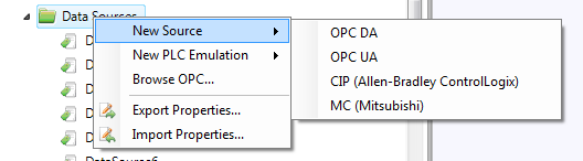
A Data Source can be defined in Sym3 using the Project Explorer > Data Sources>[Right Click] >[New Source]>[MC]
Note: Browsing is not supported for MC Data Sources.
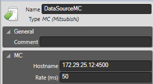
Fill in the IP address or hostname of the PLC in the Hostname field along with the port number that has been created on the PLC for MC service. The port number is required and there is no default. The format is host:port, e.g. 192.168.3.39:4500 or mitsubishi1:4500
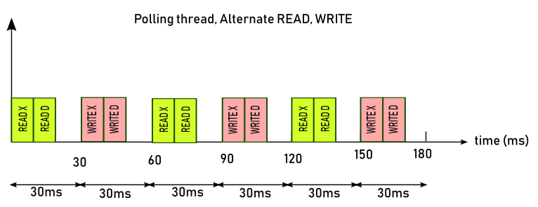
The 'Update Rate' is the value in milliseconds between two commands (READ or WRITE). This driver will READ and WRITE alternatively. The image below shows how the update rate is working.
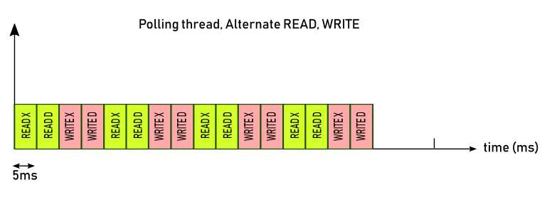
If the driver cannot keep up with the rate specified (for example 5ms) it will work in a mode called "As fast as possible":
Example of configuration:
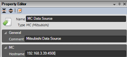
Click on the Property Editor option in the Ribbon bar to open the Property Editor Panel.
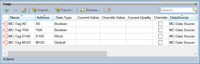
Create Tags in the Tag Manager Window using the + button.
Enter a Name for the Tag in Sym3 and the Data Source for the Tag.
Entering a Data Type for tags is optional. The default will be Boolean for bit devices and Word for word devices (refer to table below)
The Tag Address is the combination of a 1 to 3 character alphabetic Device Code mnemonic and the numeric address of the Device Point.
Please note that for this Datasource, there's no 'Update Rate' and 'Simulate Tag' properties.
By Mitsubishi’s convention, numerical device point addresses are specified in either decimal or hexadecimal radix, specified individually by device with no particular pattern as to which devices use which radix.
E.g.
The table below lists the device codes, type and address radix for the devices supported by the MC data source.
| Device Name | Code | Type | Radix | Address Min | Address Max |
| Special relay | SM | Bit | Decimal | SM0 | SM2047 |
| Special register | SD | Word | Decimal | SD0 | SD2047 |
| Input | X | Bit | Hexadecimal | X0 | X1FFF |
| Output | Y | Bit | Hexadecimal | Y0 | Y1FFF |
| Internal relay | M | Bit | Decimal | M0 | M8191 |
| Latch relay | L | Bit | Decimal | L0 | L8191 |
| Annunciator | F | Bit | Decimal | F0 | F2047 |
| Edge relay | V | Bit | Decimal | V0 | V2047 |
| Link relay | B | Bit | Hexadecimal | B0 | B1FFF |
| Data register | D | Word | Decimal | D0 | D143359 |
| Link register | W | Word | Hexadecimal | W0 | W1FFF |
| Timer Contact | TS | Bit | Decimal | TS0 | TS2047 |
| Timer Coil | TC | Bit | Decimal | TC0 | TC2047 |
| Timer Current value | TN | Word | Decimal | TN0 | TN2047 |
| Retentive Timer Contact | STS | Bit | Decimal | Not Yet Supported | Not Yet Supported |
| Retentive Timer Coil | STC | Bit | Decimal | Not Yet Supported | Not Yet Supported |
| Retentive Timer Current value | STN | Word | Decimal | Not Yet Supported | Not Yet Supported |
| Counter Contact | CS | Bit | Decimal | CS0 | CS1023 |
| Counter Coil | CC | Bit | Decimal | CC0 | CC1023 |
| Counter Current value | CN | Word | Decimal | CN0 | CN1023 |
| Link special relay | SB | Bit | Hexadecimal | SB0 | SB7FF |
| Link special register | SW | Word | Hexadecimal | SW0 | SW7FF |
| Direct access input | DX | Bit | Hexadecimal | Not Yet Supported | Not Yet Supported |
| Direct access output | DY | Bit | Hexadecimal | Not Yet Supported | Not Yet Supported |
| Index register | Z | Word | Decimal | Not Yet Supported | Not Yet Supported |
| File register - Block switching method | R | Word | Decimal | Not Yet Supported | Not Yet Supported |
| File register - Serial number access method | ZR | Word | Hexadecimal | Not Yet Supported | Not Yet Supported |
Sym3 supported data types:
• Default
• Boolean
• Char
• Byte
• Short
• Word
• Long
• DWord
Conversions:
The Mitsubishi Q/L Series PLCs devices are either of 2 fundamental data types, bit or 16-bit word.
When code in the PLC generates 32 or 64 bit values in word device memory, occupying 2 or 4 device points respectively, the values are ordered in little-endian format and addressed accordingly with the lowest device point address being the least significant 16 bits of the larger type.
There is no ability to address or atomically write a single bit to a word device, therefore bit addressing for word devices is not supported.
When converting between the PLC types and the Sym3 types the following rules apply
Bit devices:
• When reading tag values for any bit device mapped to any of the Sym3 integer types the value of the bit device will be represented in bit 0 of the integer with the remaining bits having the value of zero.
• When setting tags, for any integer Sym3 type, the bit device will be set with the value from bit 0 of the integer and all other bits ignored.
Word devices:
• When reading or writing tag values for any word device mapped to a Sym3 Boolean type the data is read from or written to bit 0 of the addressed device point.
• When reading or writing tag values for any word device mapped to a Sym3 Byte or Char type the data is read from or written to bits 0-7 of the addressed device point.
• When reading or writing tag values for any word device mapped to any of the Sym3 integer types the usual rules apply for the promotion and demotion of integer types.
• When reading or writing tag values for any word device mapped to any of the Sym3 32 or 64 bit integer types the address of the data is the lowest device point word address.